Build Guide
Welcome to the build guide. This guide will go through building a Blue Team Pad from scratch. If yours is already built skip straight to the usage guide. If you need to source these parts visit the ordering guide
If you need to make any image bigger, right click on it and select Open Image in New Tab. This will open the image in a new tab and allow you to zoom in on it.
Building the Blue Team Pad from scratch requires soldering!
Part Overview
You should have the following parts before you start the build:
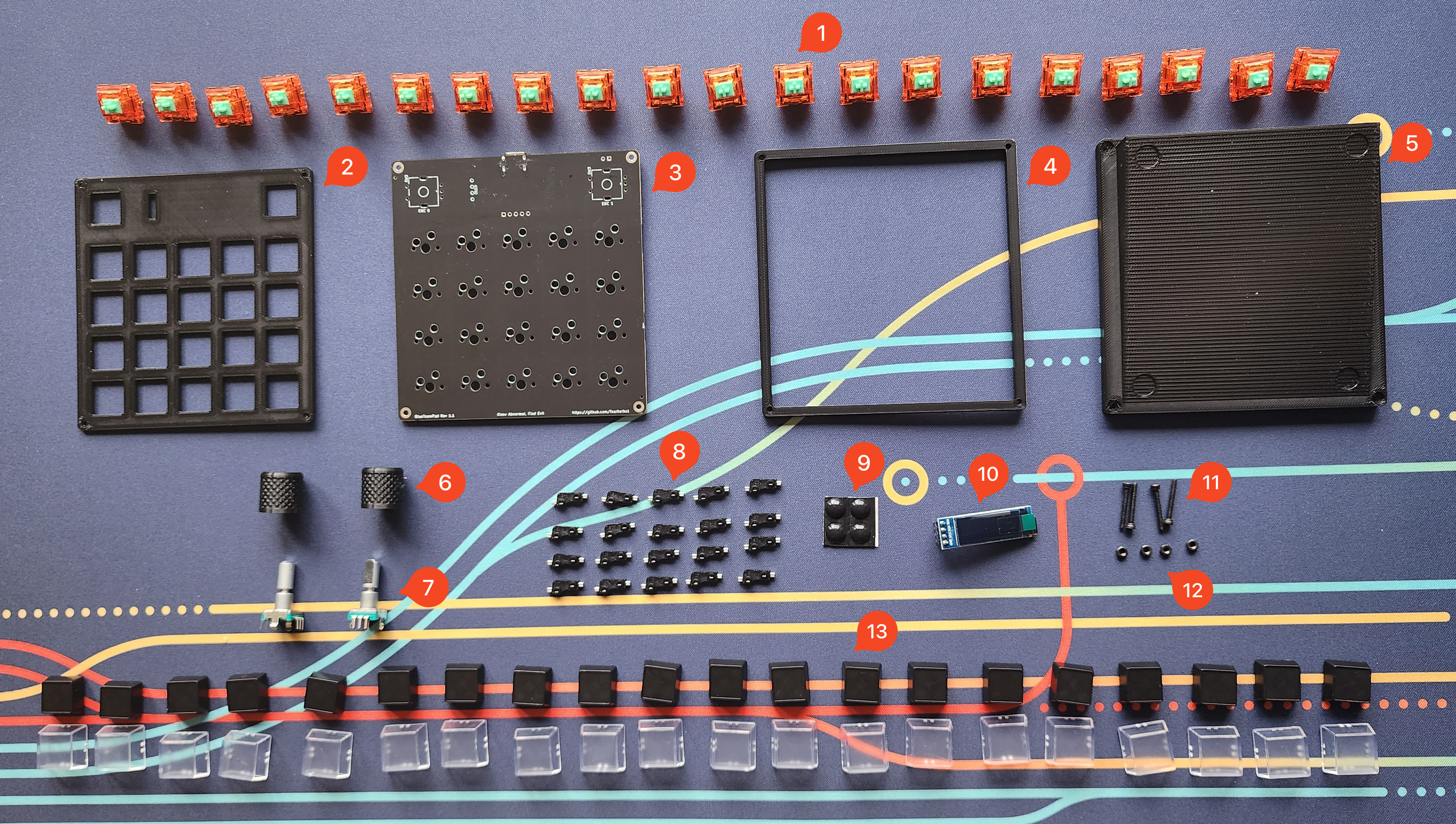
Parts List
- 20 MX Style Switches of Your Choice
- 1x Plate
- 1x PCB
- 1x Case Mid Piece
- 1x Case Bottom Piece
- 2x Knobs
- 2x EC11 Encoders LCSC Link
- 20x Kalith or Gataron MX Hotswap Sockets
- 4x Rubber Bumpons (8mm Diameter)
- 1x OLED
- 4x M2 Machine Screws (16mm)
- 4x M2 Nuts
- 20 Keycaps of Your Choice
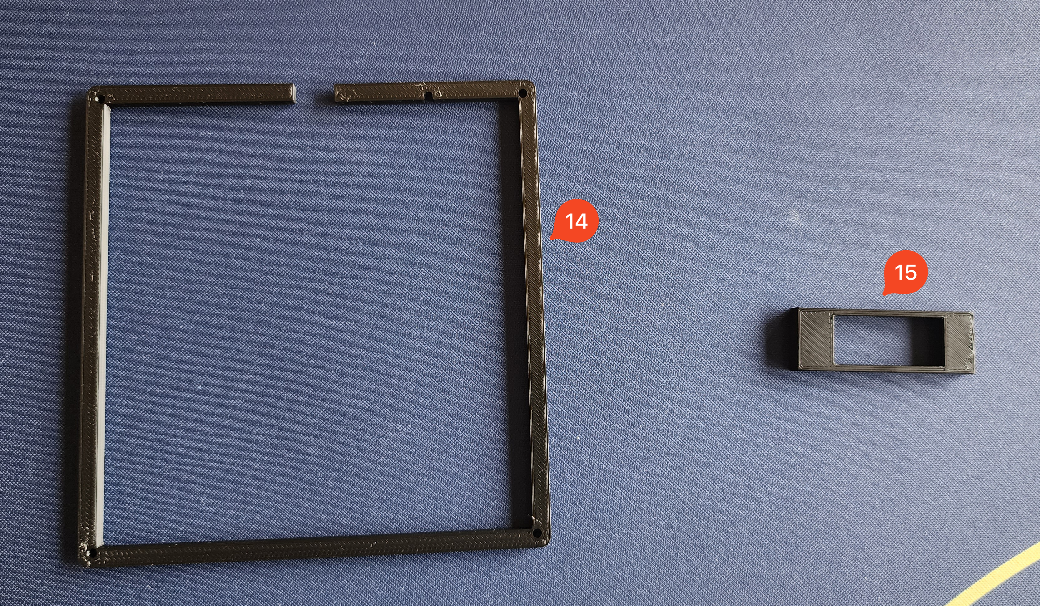
- 1x Case USB Mid Piece
- 1x OLED Cover (Oled Socket Version or Standard Version)
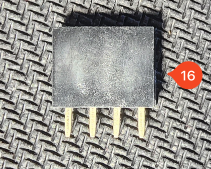
- 1x OLED Socket (Optional)
Tool Overview
You will need the following tools to complete the build:
- Soldering Iron
- Solder (Lead Preferred)
- 2 Pairs of Metal Tweezers or 2 Paperclips
- 1.5mm Hex Screw Driver or allan key
- 1 USB Type C Cable
- Computer that can run VIAL
Step 1: Testing the PCB & OLED
Before we do anything, we want to make sure our PCB & OLED is working as expected. Launch VIAL on your PC and connect the PCB.
If the Blue Team Pad is not recognized within VIAL, or shows up as a USB storage device named RPI-RP2 you may need to flash the firmware on the device. To do so visit the Flashing Guide
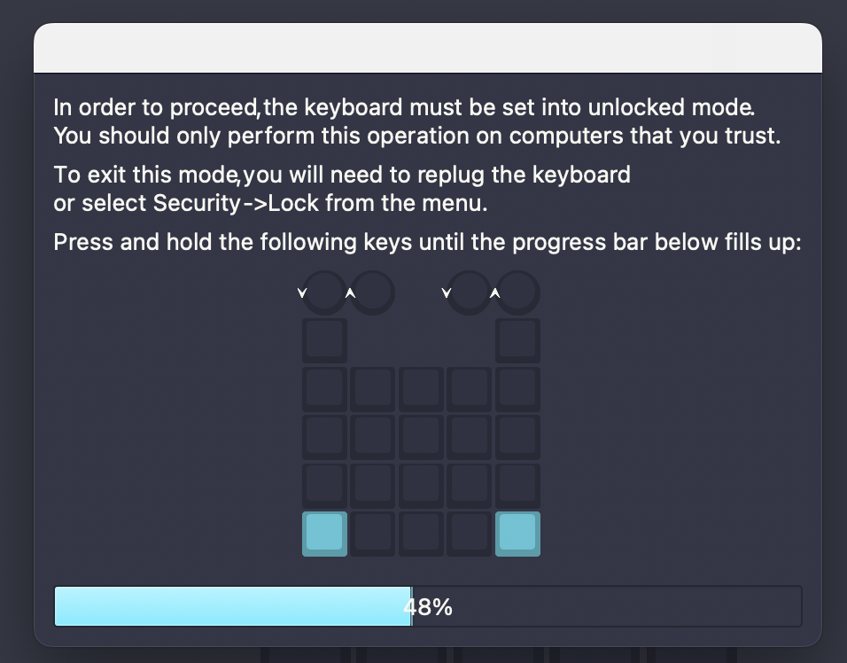
Once connected Navigate to the Matrix Tester Tab within VIAL and click the Unlock Keyboard button in the bottom right.
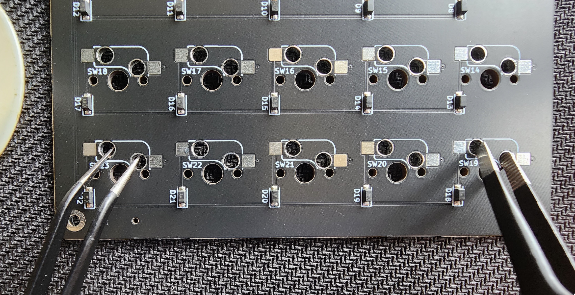
Now, since the pad is not built, we will need to use our metal tweezers / paperclips to short the two unlock connections. This process can be done by shorting both the SW23 and SW19 pads at the same time until the bar fills on VIAL:
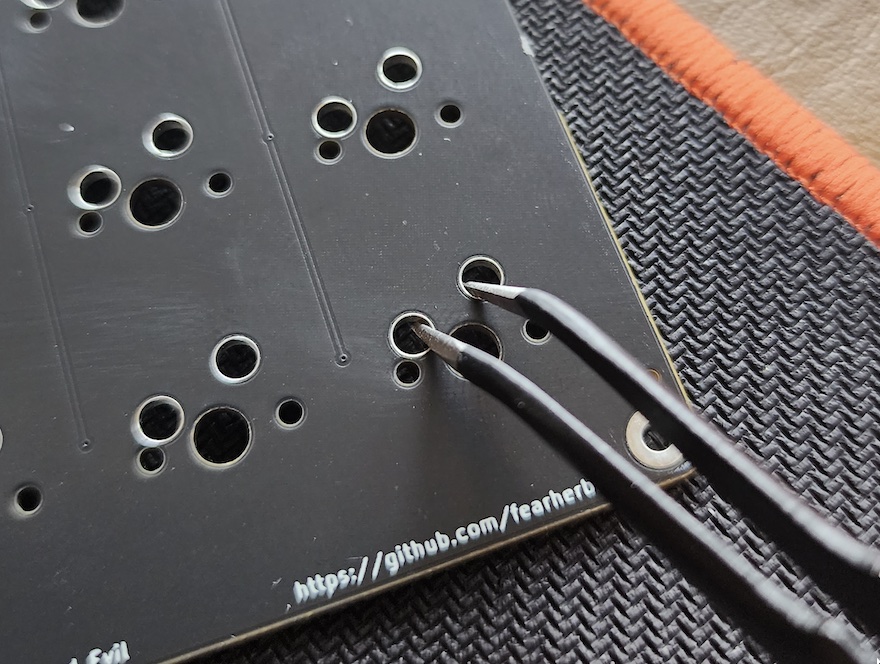
Once unlocked, use your pair of tweezers / paperclip to short each switch pad on the PCB.
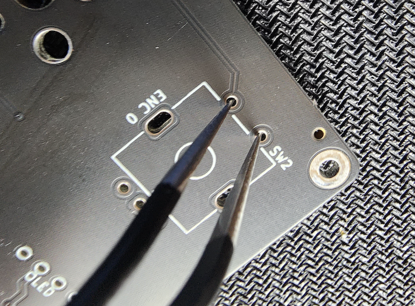
Then short the 2 pads corresponding to the switch for each encoder.
These will be the 2 pins closest to the SW2 & SW3 markings on the PCB:
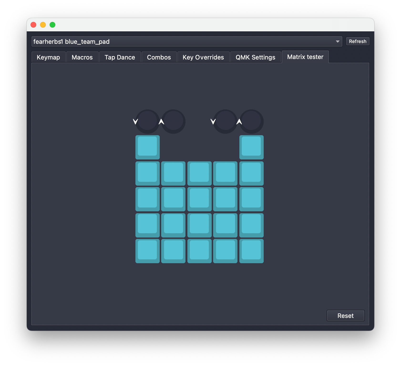
If your PCB is fully functional, every key should be blue on VIAL as shown below:
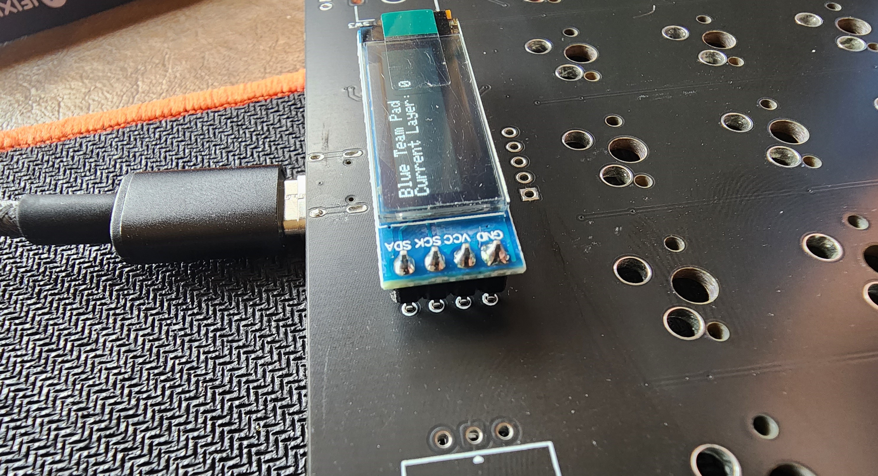
To test the OLED, first unplug the PCB from your PC. Then place the OLED within it’s footprint on the top of the PCB as shown below so the pins make contact with the pads. Then plug the PCB back in. The OLED should light up and display Layer information as well as the name of the pad:
Step 2: Soldering Hot Swap Sockets
Now that we have all of our tools, parts & the PCB is tested we can begin the build.
First we will solder the hot swap sockets to the PCB.
Set up your solder iron and gather the PCB & 20x hot swap sockets.
One at a time place & solder each hot swap sockets within the designated areas on the pcb. These areas are marked SW4 through SW23
Ensure that your sockets are facing the correct direction! The pads will still line up if the part is flipped upside down! Refer to the photo below as a reference.
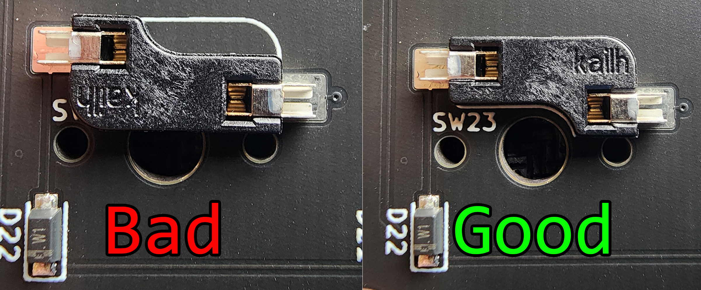
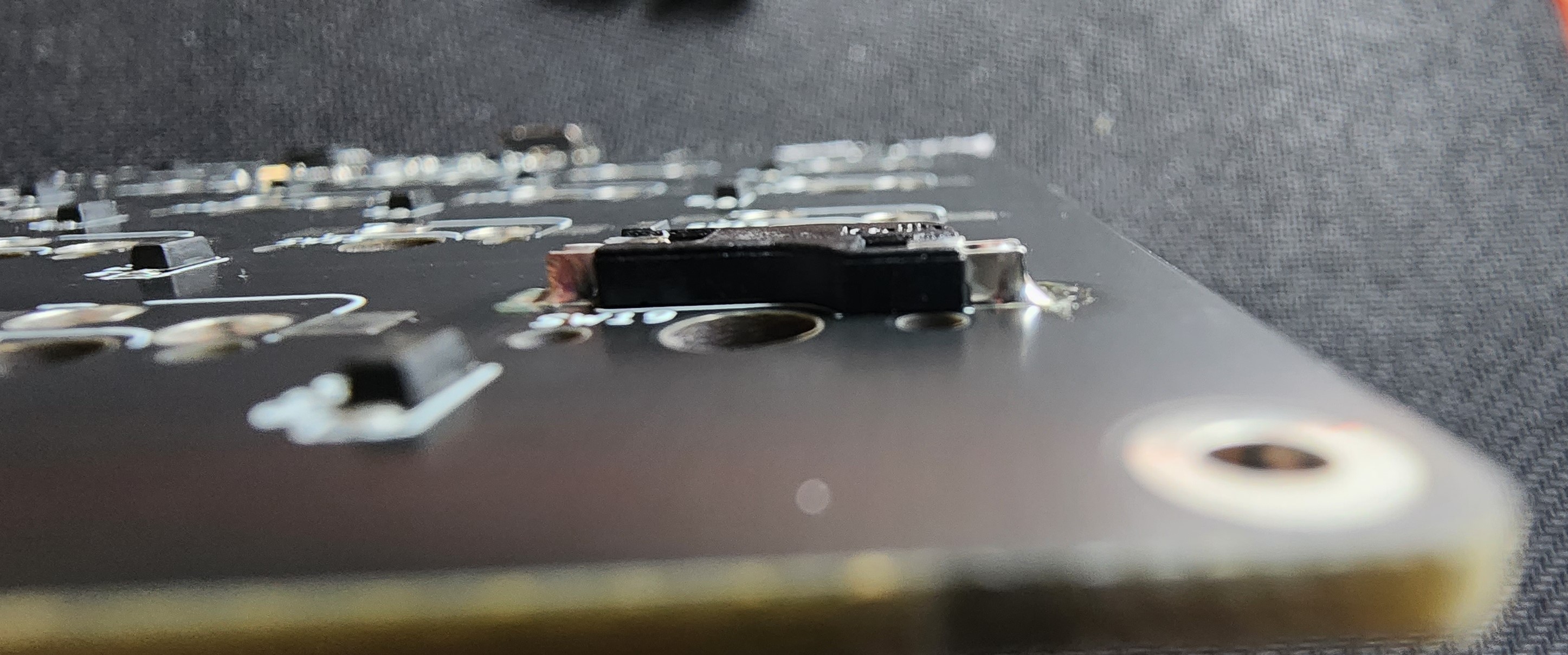
When soldering the sockets, ensure that each one is flush with the PCB as seen below:
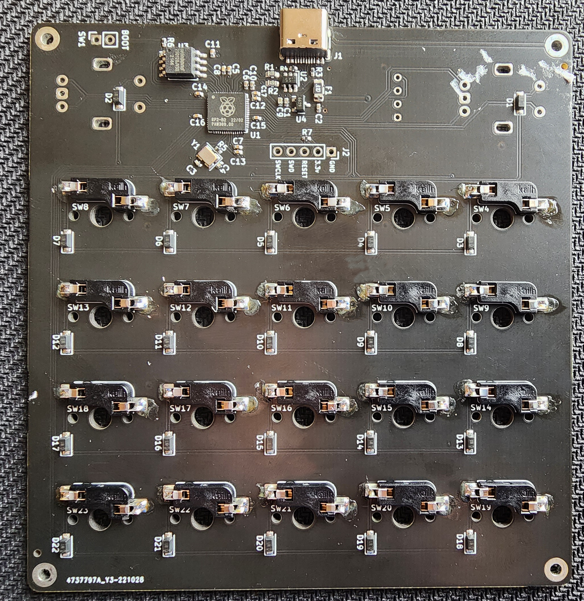
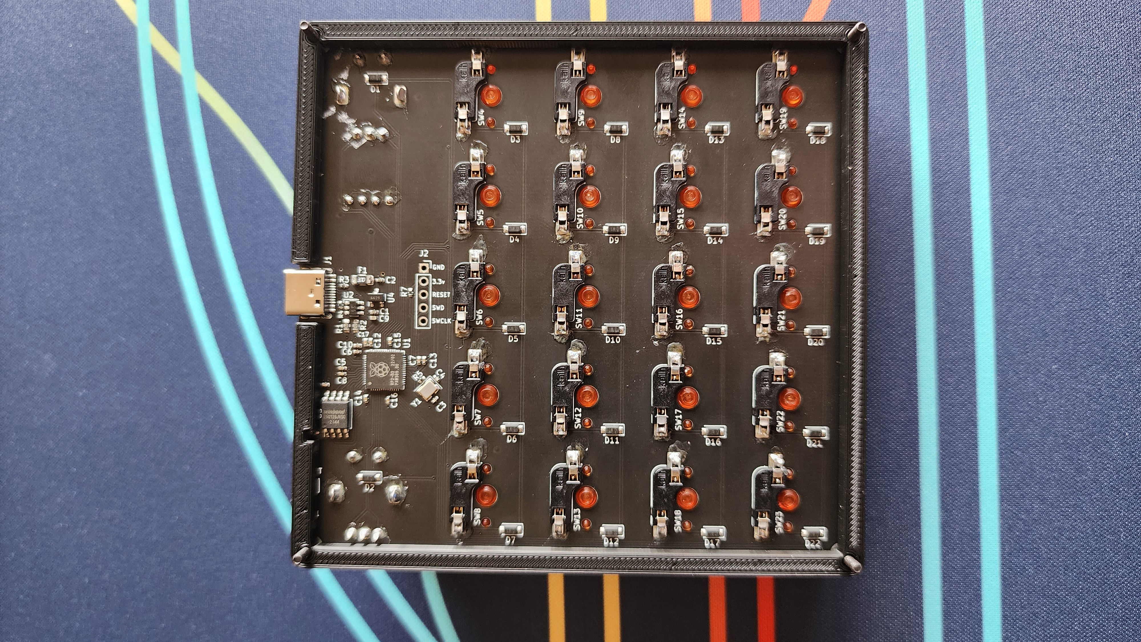
When you are finished soldering the sockets, your PCB should look like the following:
Step 3: Soldering Encoders
Next we will solder the two encoders to the PCB.
Line up each encoder and fit the pins within the ENC 0 and ENC 1 footprints on the PCB.
These will be soldered on the OPPOSITE side of the PCB compared to the hot swap sockets. Also ensure the encoders are flush before soldering them!
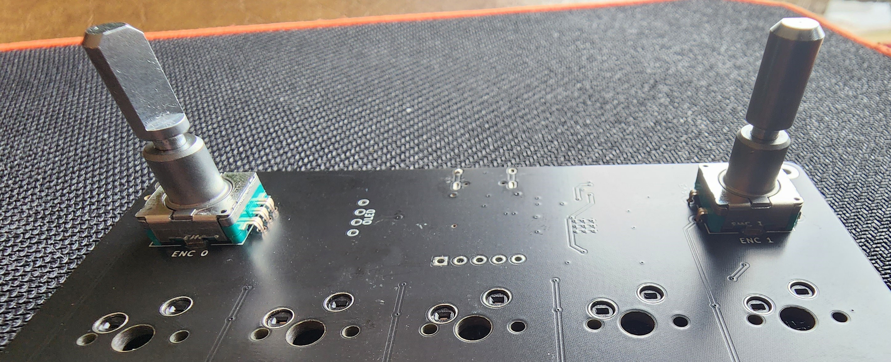
While the 2 larger “pins” do not carry any electrical current, they serve as a way to stabilize the encoder on the PCB, so be sure to solder them.
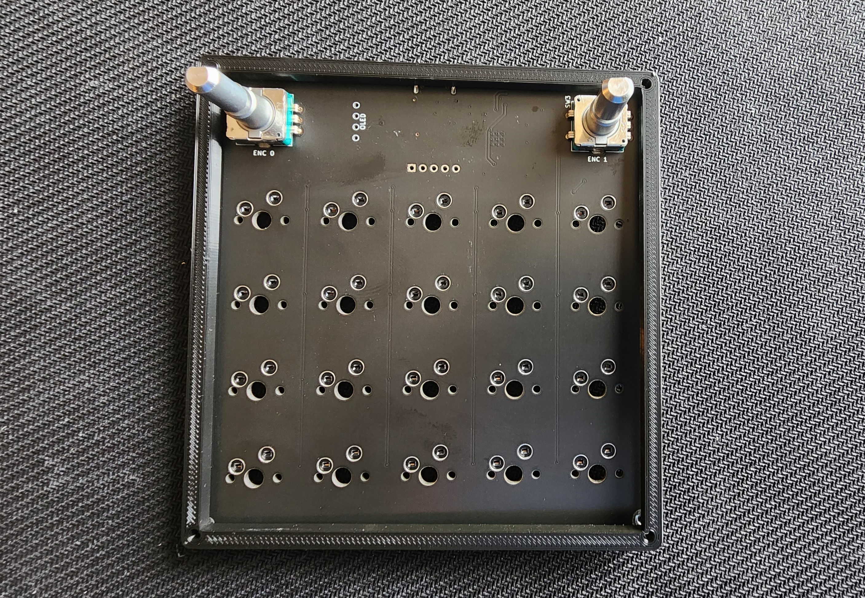
Once done your encoders’ solder joints should look like the following:
Step 4: Assemble The Case
First, gather the following case parts:
- 1x Case Mid Piece (The one without the USB cutout!)
- 1x Plate
- 20x MX Switches
First line up the mid piece with the PCB as shown below:
All of the case parts are NOT a perfect square, so you may need to rotate them to in order for the holes to line up.
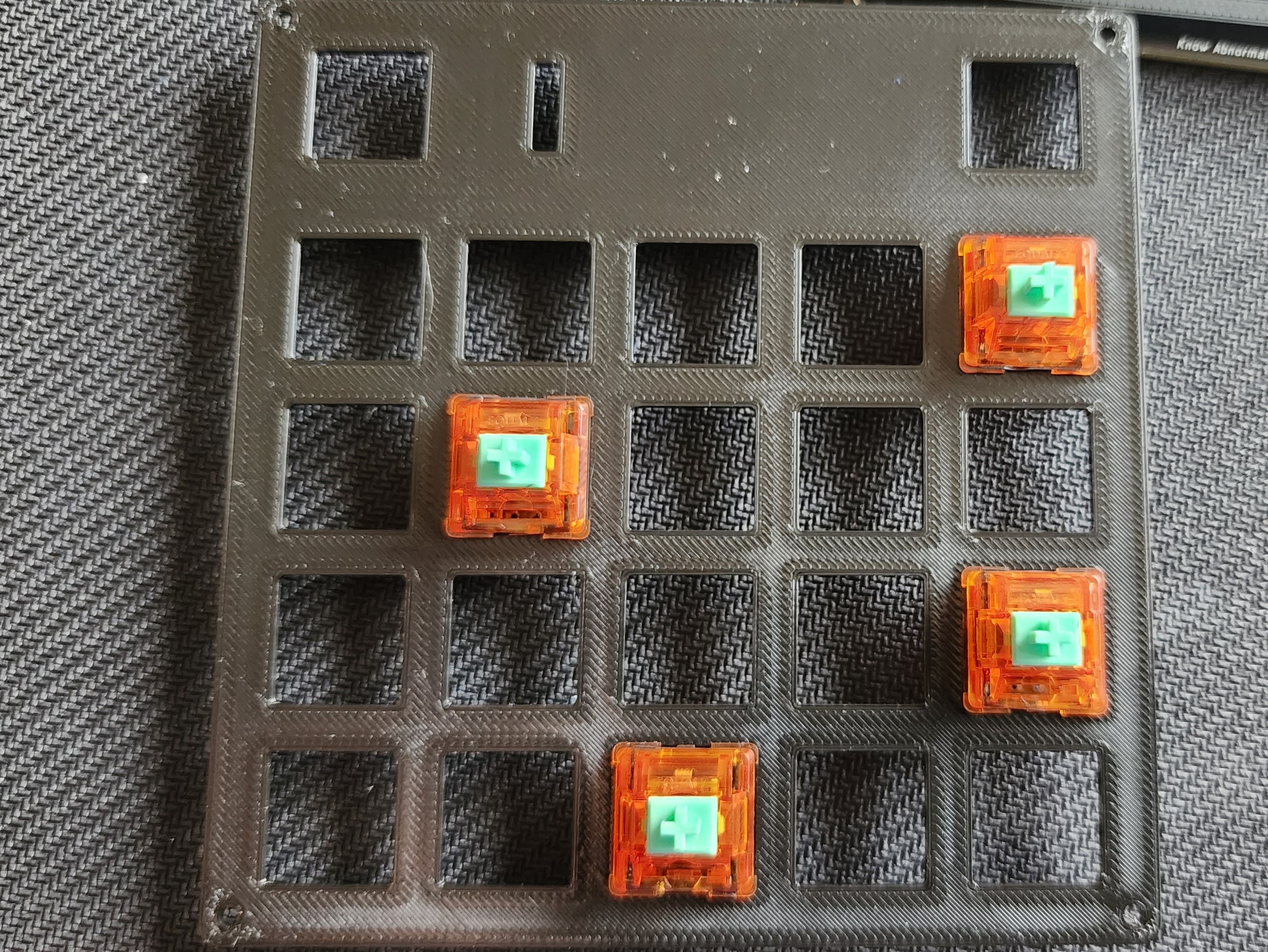
Next grab the place and inset a few switches into the plate. Be SURE that the switches are inserted into the plate in the correct orientation.
The little rectangle on top of the plate must be on the left side, and the switches must be south facing. By south facing we want the LED hole to be facing south and the branding to be facing north. See the photo below for reference:
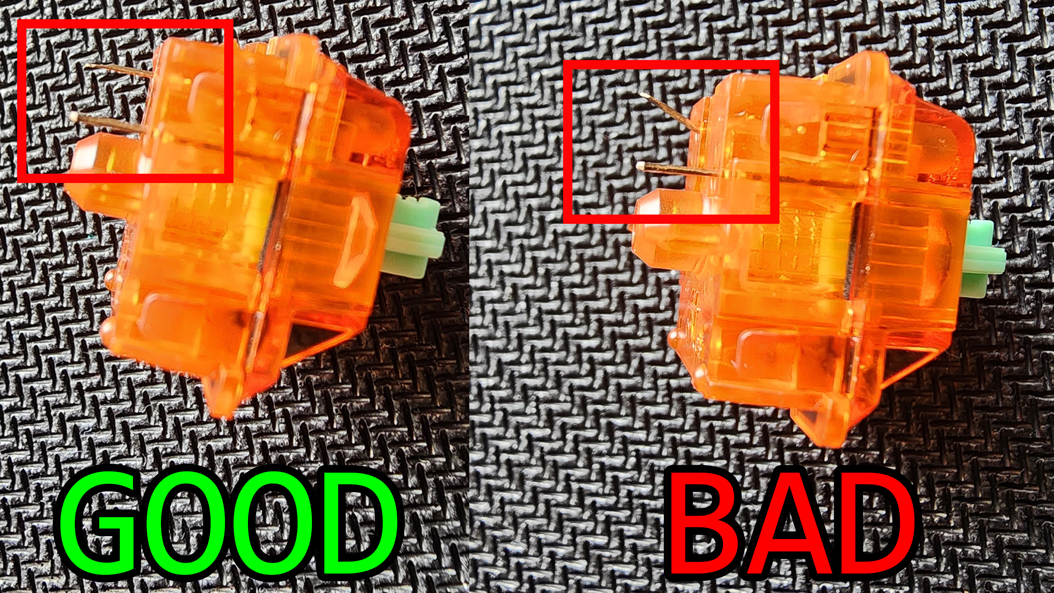
You must ensure that your switch pins are not bent! If they are bent, the switches will not fit into the hot swap sockets properly and this will prevent the switch in question from working.
Refer to the photo below for reference:
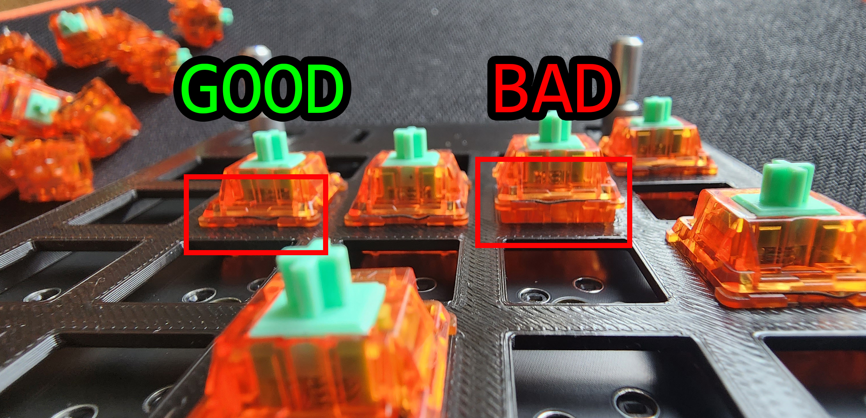
Next, place the plate on top of the mid piece & pcb while simultaneously inserting the switches into the hot swap sockets. Be sure to line up the holes on the plate with the holes on the mid piece.
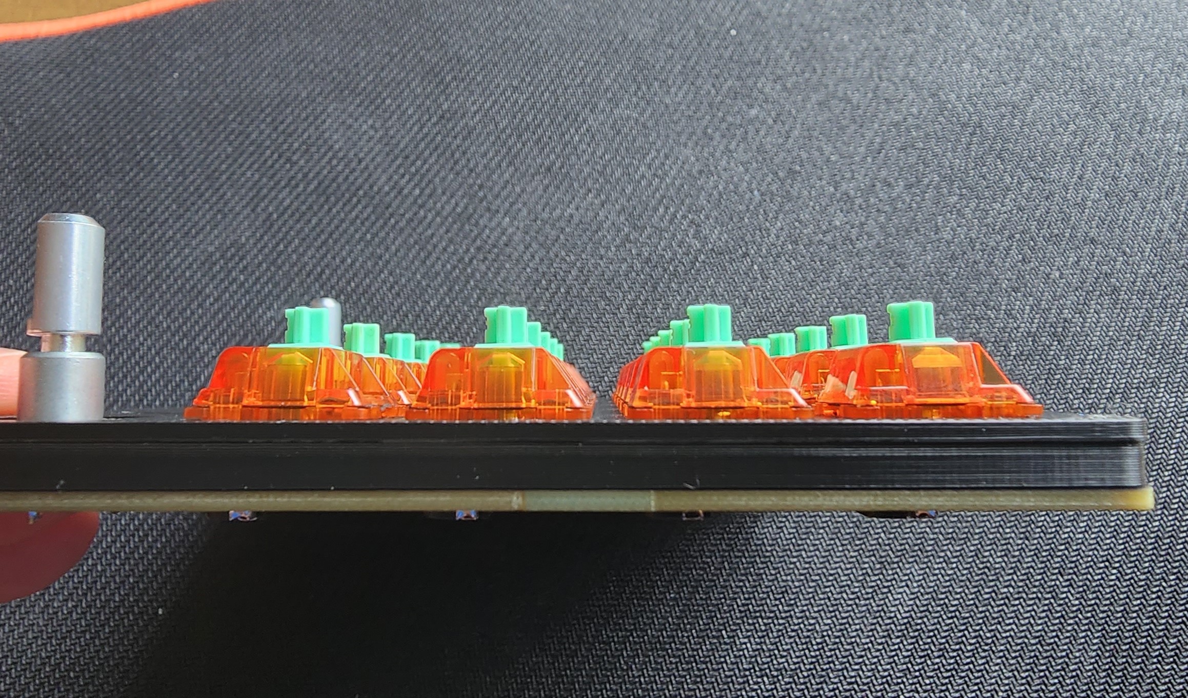
Be sure that once inserting the switches they are flush with the plate as shown below:
Then Insert the rest of the switches, once again be sure to check every switch for bent pins!
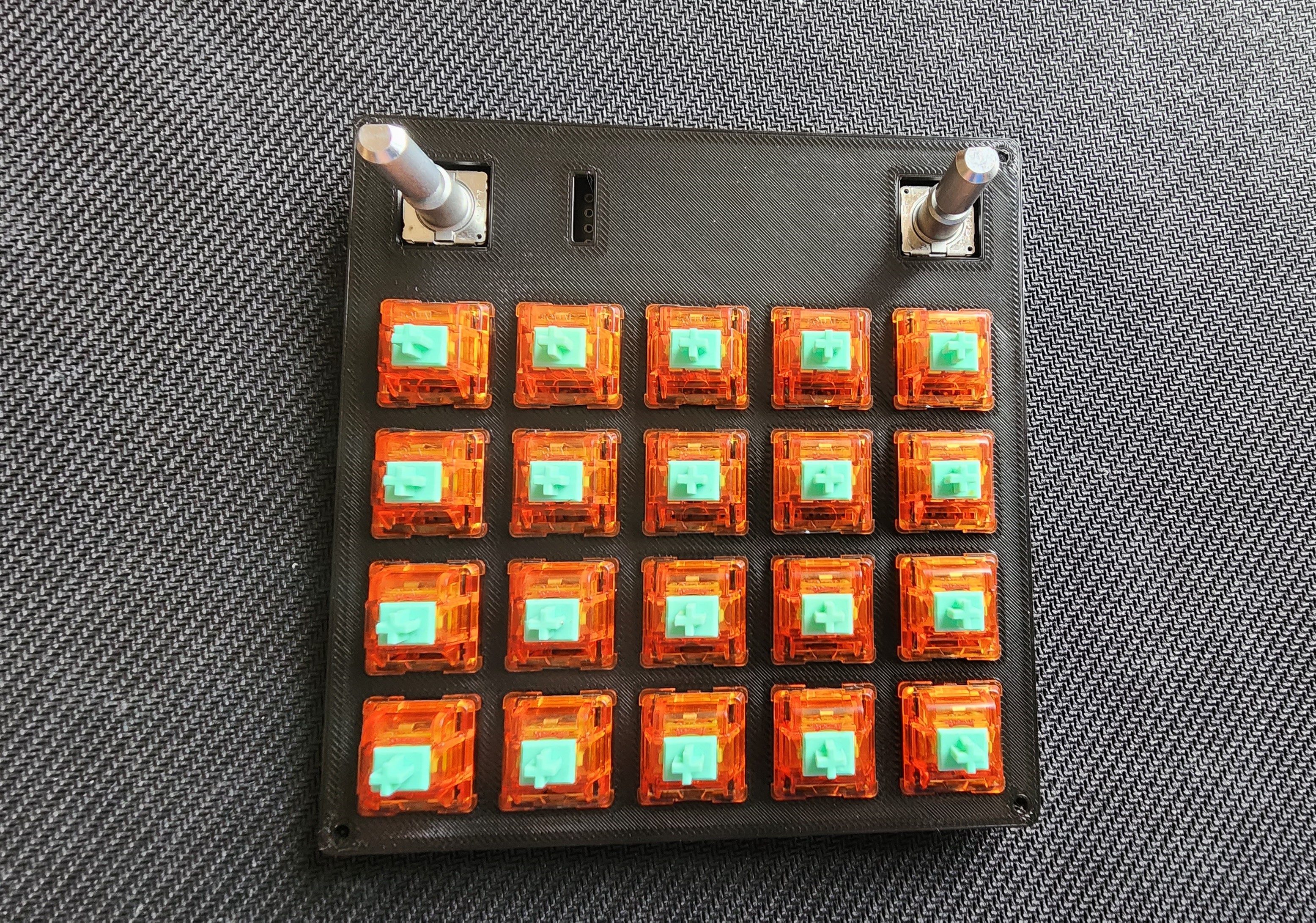
Once all of the switches are inserted, double check one last time to ensure that all of the switches are inserted correctly.
Step 5: Soldering the OLED (no socket)
If you chose purchase an OLED socket, skip to step 5.1
Before we solder our OLED, lets install the OLED cover. This will help protect the OLED from damage after installation.
First remove the protective film from the OLED. In this case it looks like a screen protector with a green pull tab.
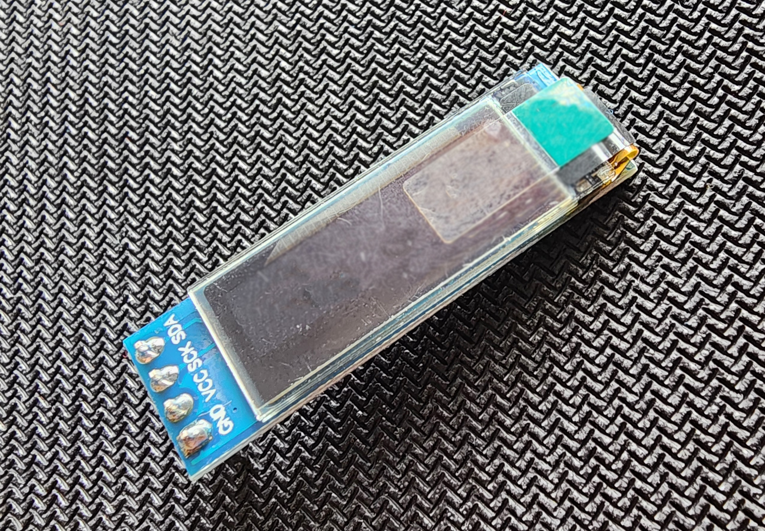
Be sure to install the OLED cover with the correct orientation! If installed incorrectly, the OLED CAN be damaged! (2 OLEDs were broken in the process of prototyping this part)
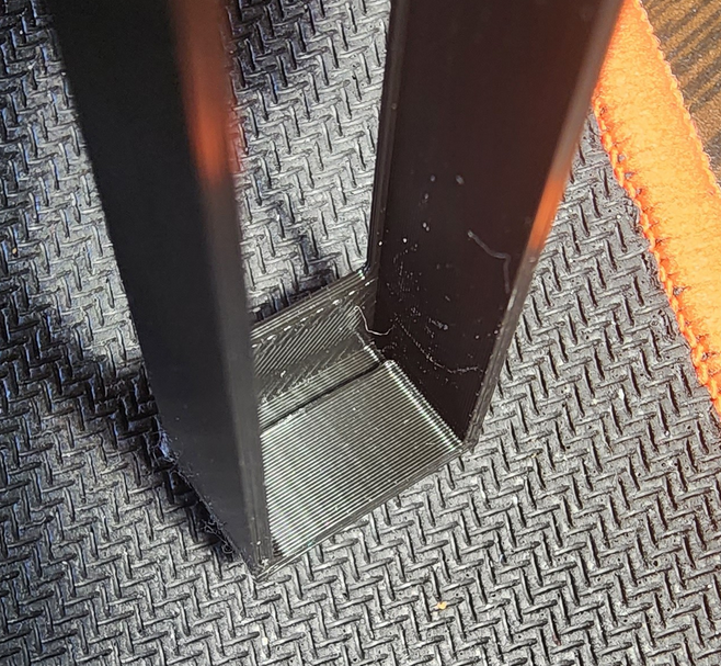
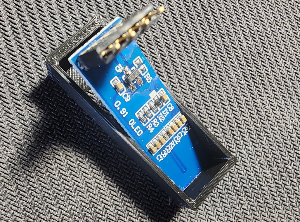
If you look at the inside of the OLED cover closely, you will notice that the inside of one side of the cover has a small notch. This notch is meant for extra space for the ribbon cable that connects the OLED to it’s PCB.
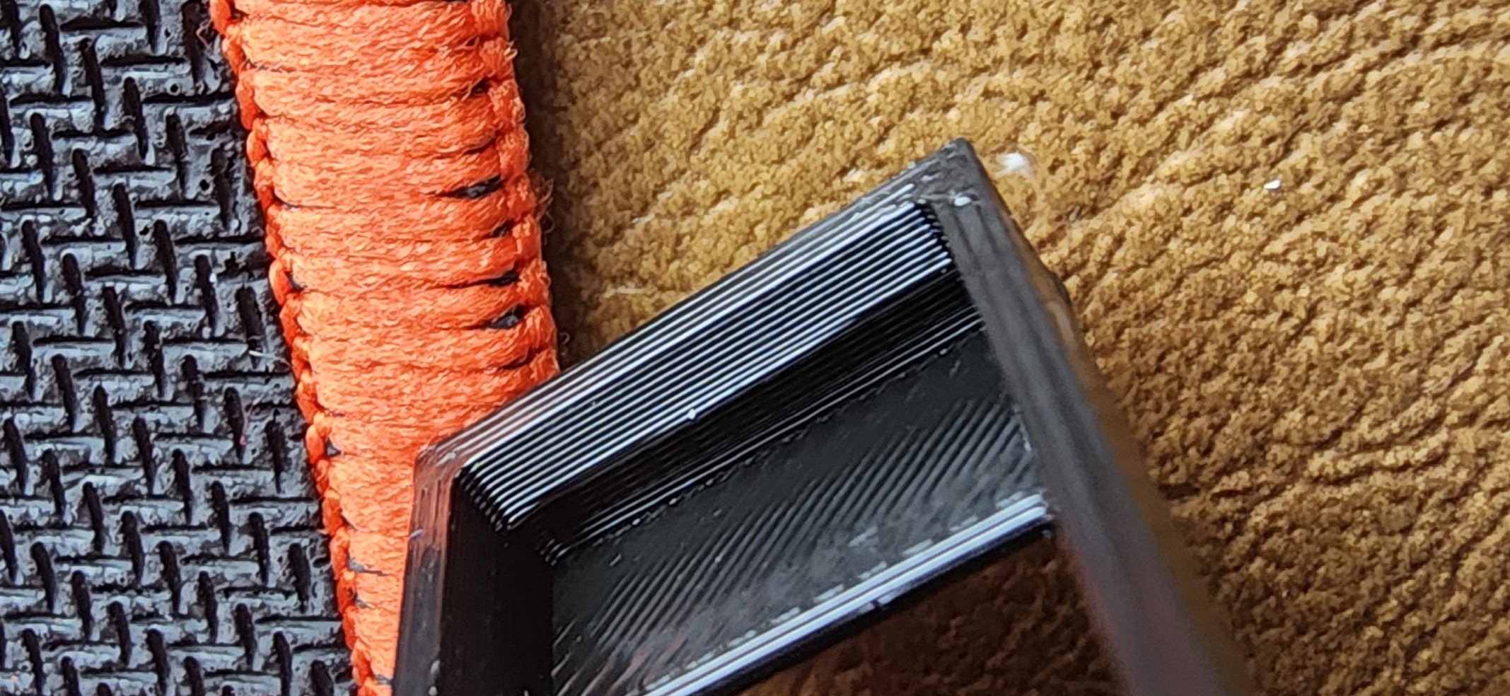
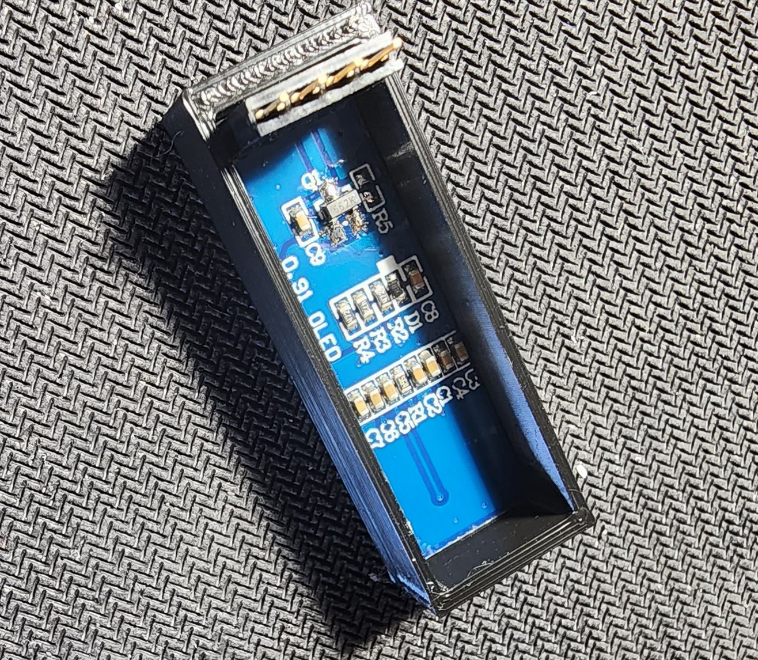
Then place the OLED into the OLED cover by first inserting the side without pins into the cover so the ribbon cable slots into the aforementioned notch:
Then press the side with the pins into the cover. It should fit snugly.
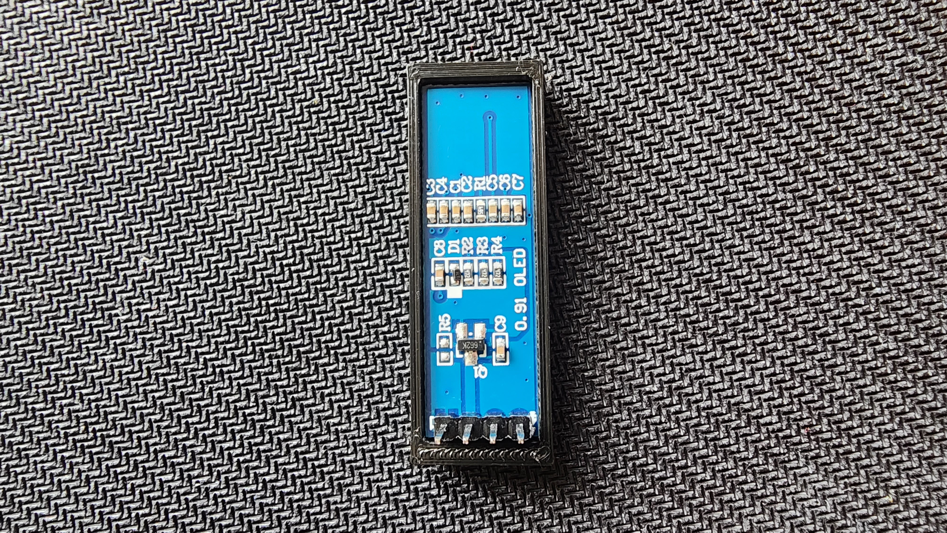
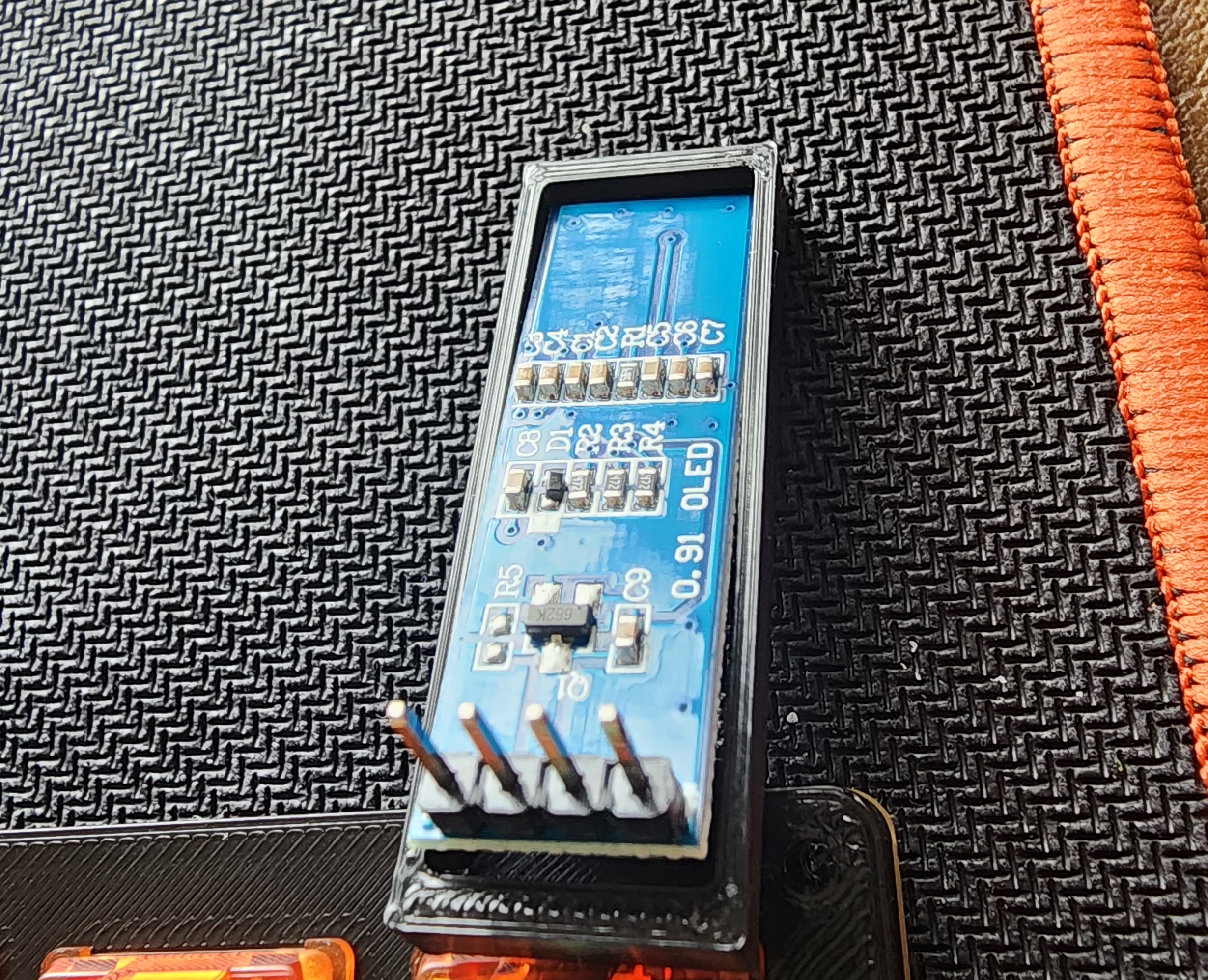
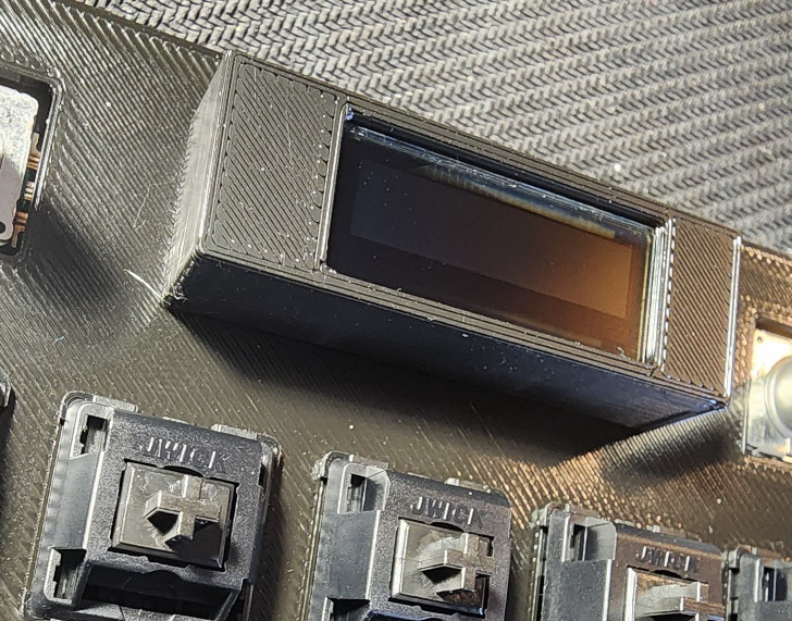
Then insert the OLED through the plate so the pins fit into the PCB as shown below:
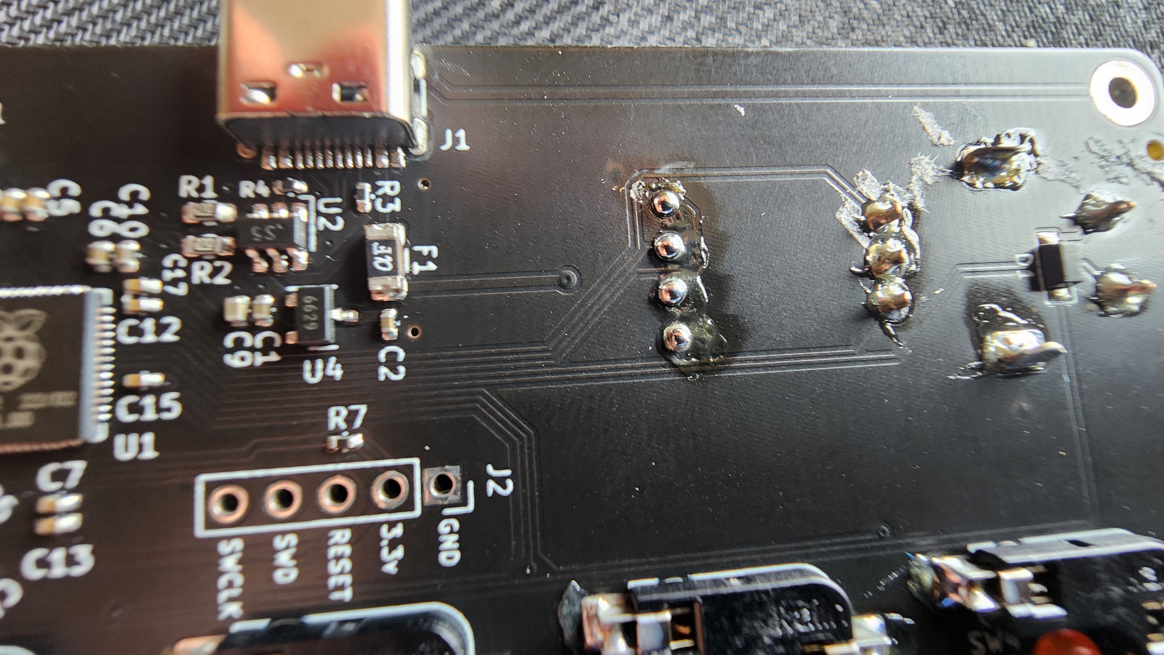
Then solder the 4 OLED pins to the PCB as shown below:
Step 5.1: Soldering the OLED (socket)
Before we solder our OLED, lets install the OLED cover. This will help protect the OLED from damage after installation.
First remove the protective film from the OLED. In this case it looks like a screen protector with a green pull tab.
Be sure to install the OLED cover with the correct orientation! If installed incorrectly, the OLED CAN be damaged! (2 OLEDs were broken in the process of prototyping this part)
If you look at the inside of the OLED cover closely, you will notice that the inside of one side of the cover has a small notch. This notch is meant for extra space for the ribbon cable that connects the OLED to it’s PCB.
Then install the socket on the OLED by pressing it into the socket as shown below:
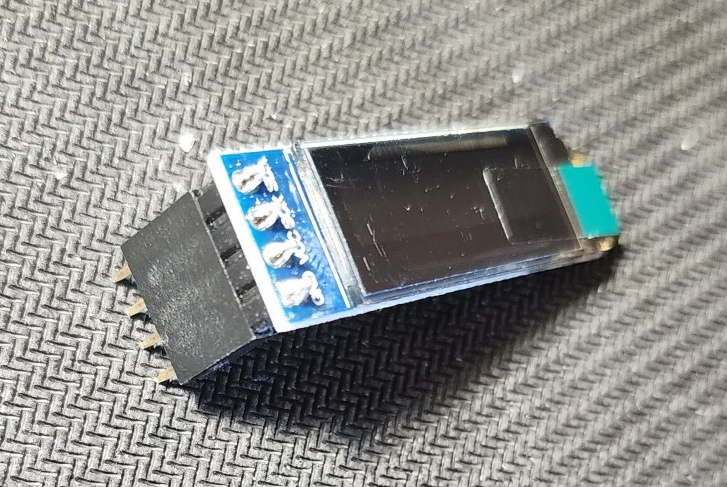
Then place the OLED into the OLED cover by first inserting the side without pins into the cover so the ribbon cable slots into the aforementioned notch:
Then press the side with the pins into the cover. It should fit snugly.
Then insert the OLED with the socket attached through the plate so the pins fit into the PCB as shown below:
Then solder the 4 OLED pins to the PCB as shown below:
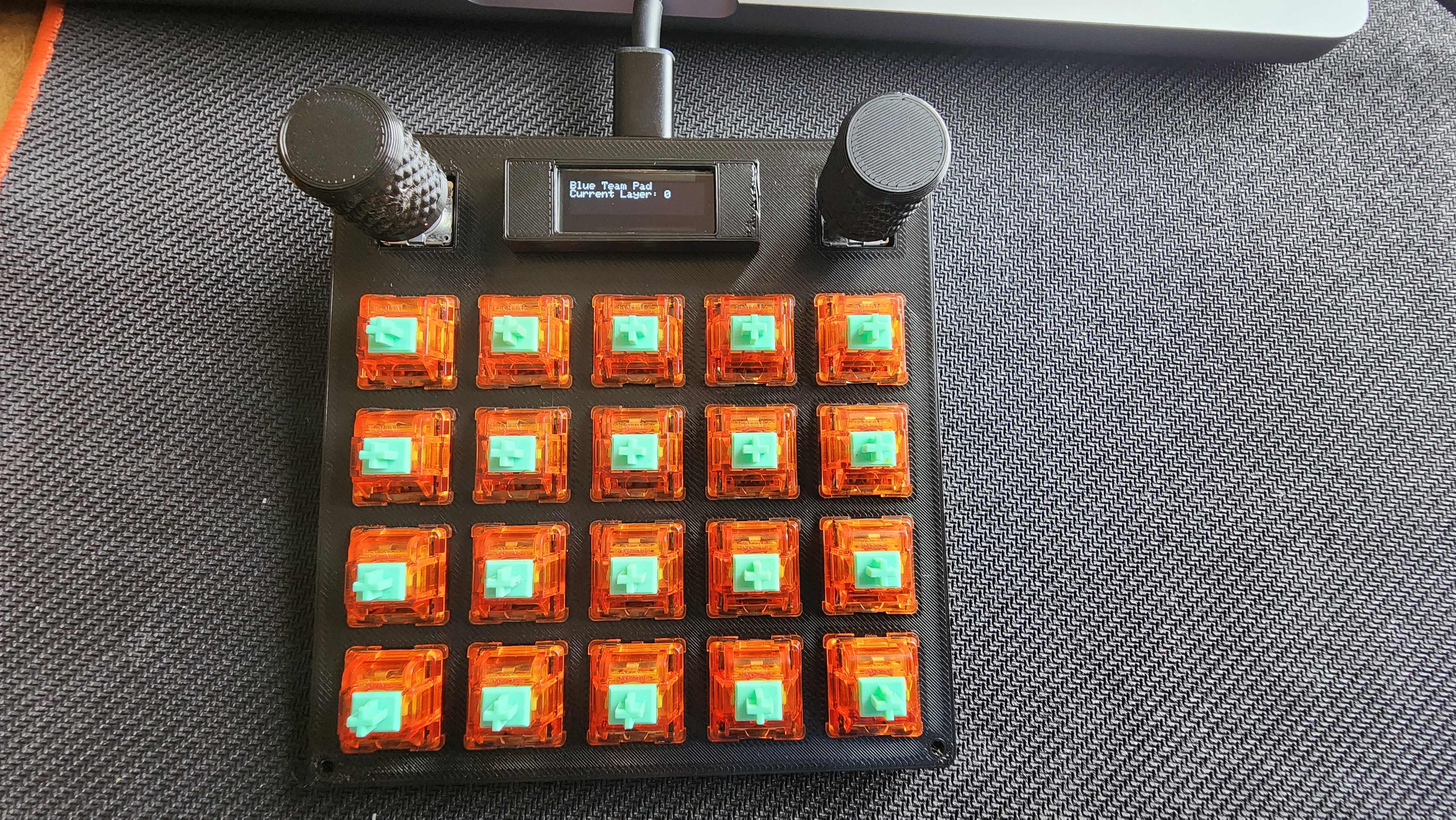
Step 6 Testing the OLED & Switches
Now that all of the electronics are assembled we can check to make sure everything is working properly.
First, plug in the macro pad into your computer and connect it to VIAL.
The OLED should light up and display the current layer and Blue Team Pad.
The OLED will go into sleep mode after ~60 seconds of inactivity. To wake it up, press any key on the pad. This is to prevent OLED burn-in.
Then just how we first tested the pcb, navigate to the matrix tab, unlock the Pad, and press each switch to ensure that they are working properly.
Every switch should light up when you push it. If a switch does not, remove it and check the pins to ensure that they are not bent.
Step 7: Finish Case Assembly
Now that we have confirmed that the electronics are working properly, we can finish assembling the case.
First, grab the 4x m2x16mm screws and insert them through each hole in the corners of the plate as shown below:
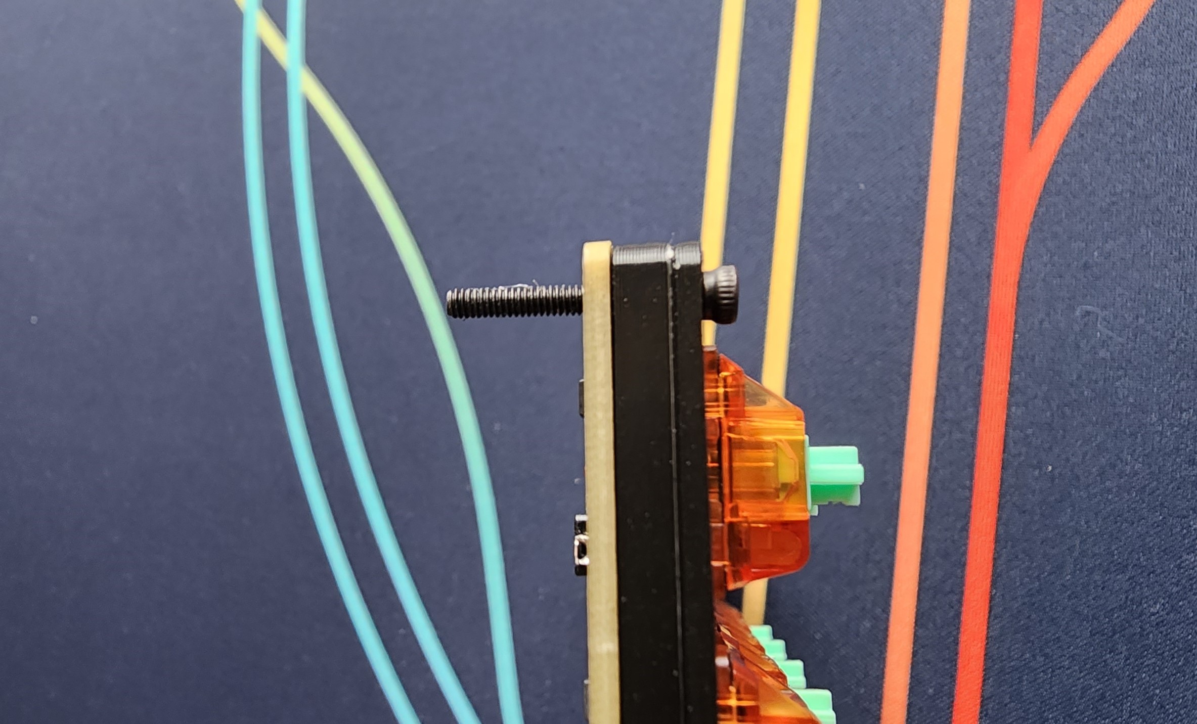
You may have to use your screwdriver to “screw” your screws through the 3d printed parts during assembly, this is by design to ensure a snug case assembly.
Then grab the mid piece with the USB cutout and place it on the PCB, screwing it into the 4 screws.
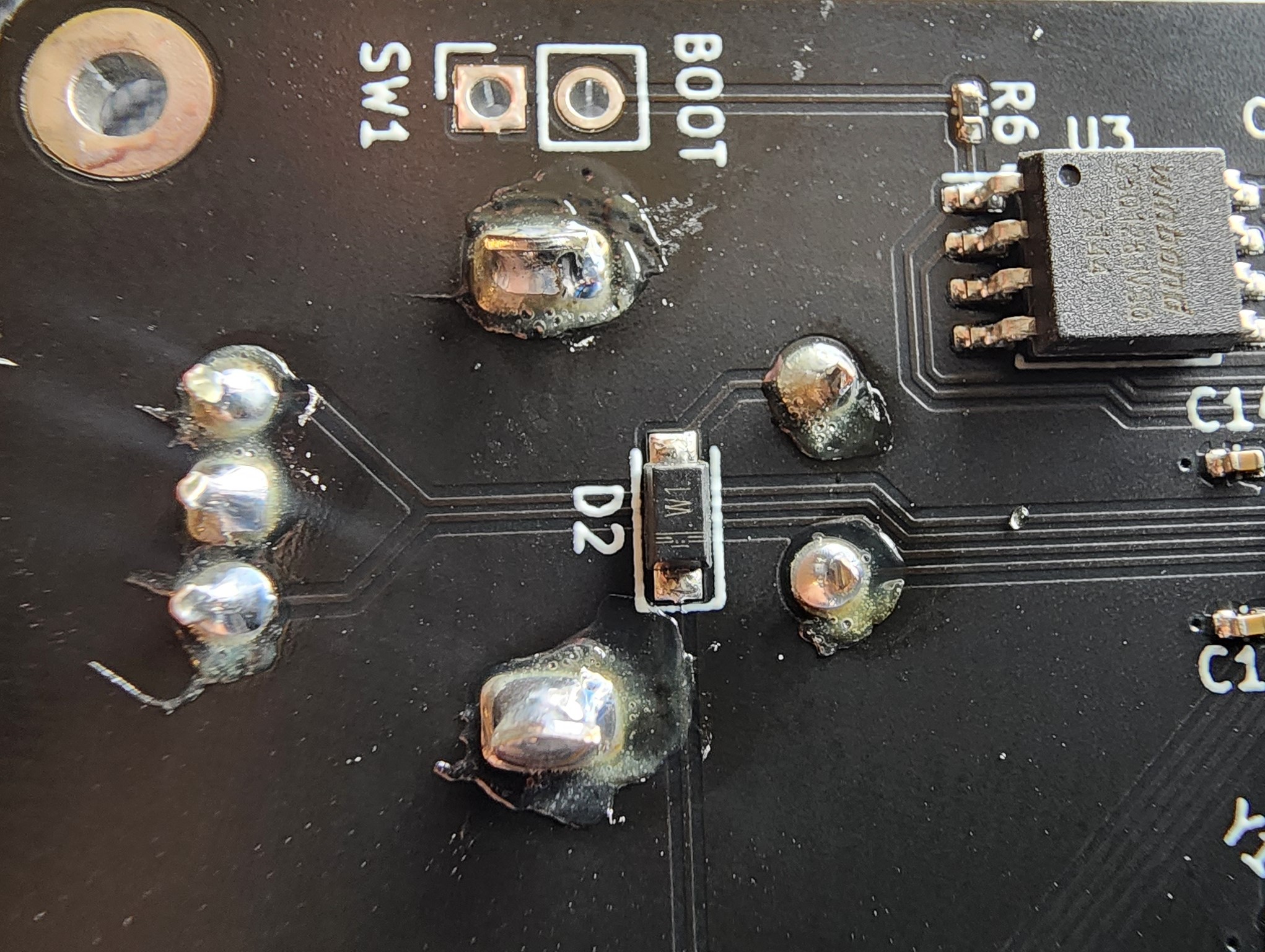
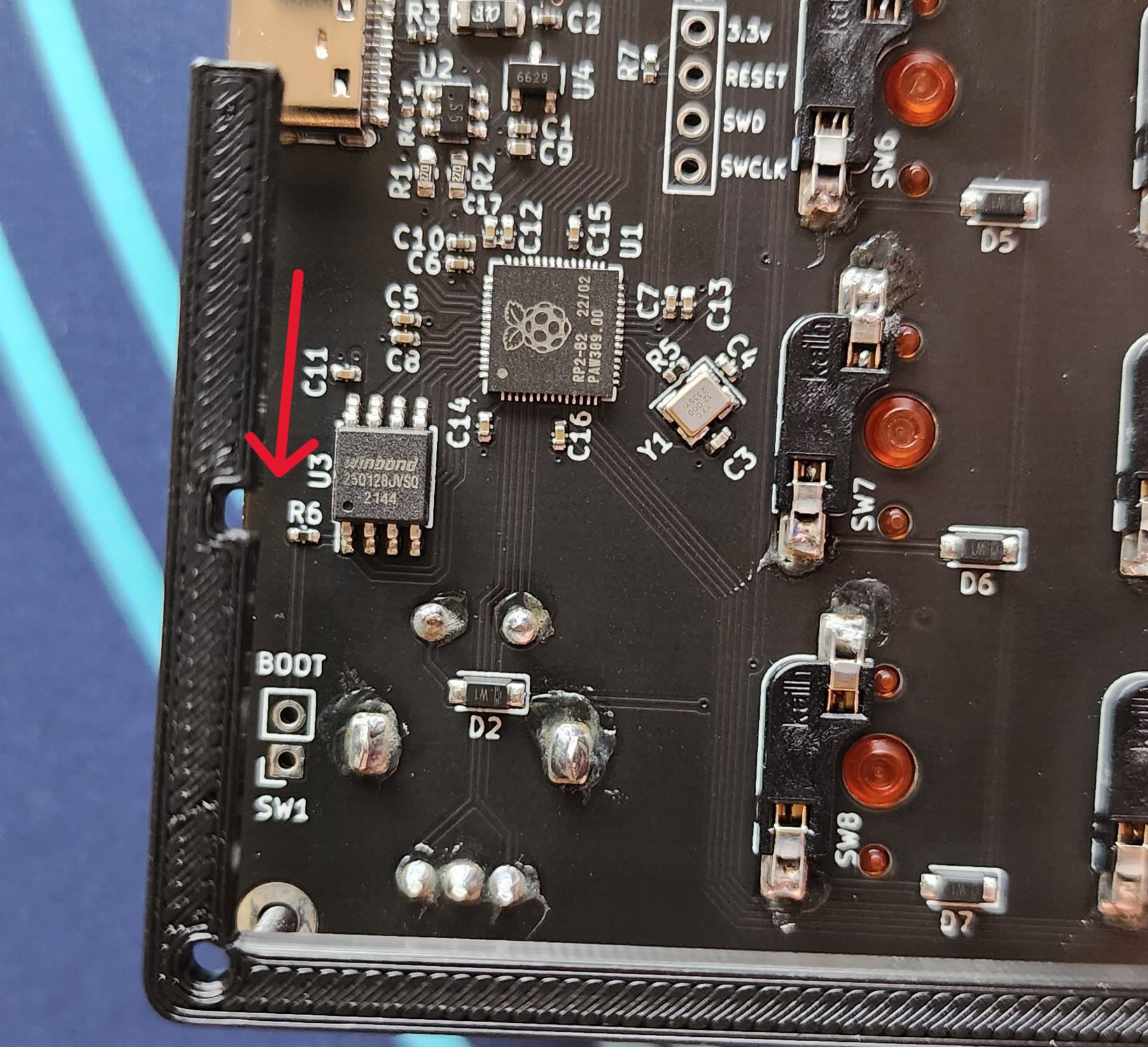
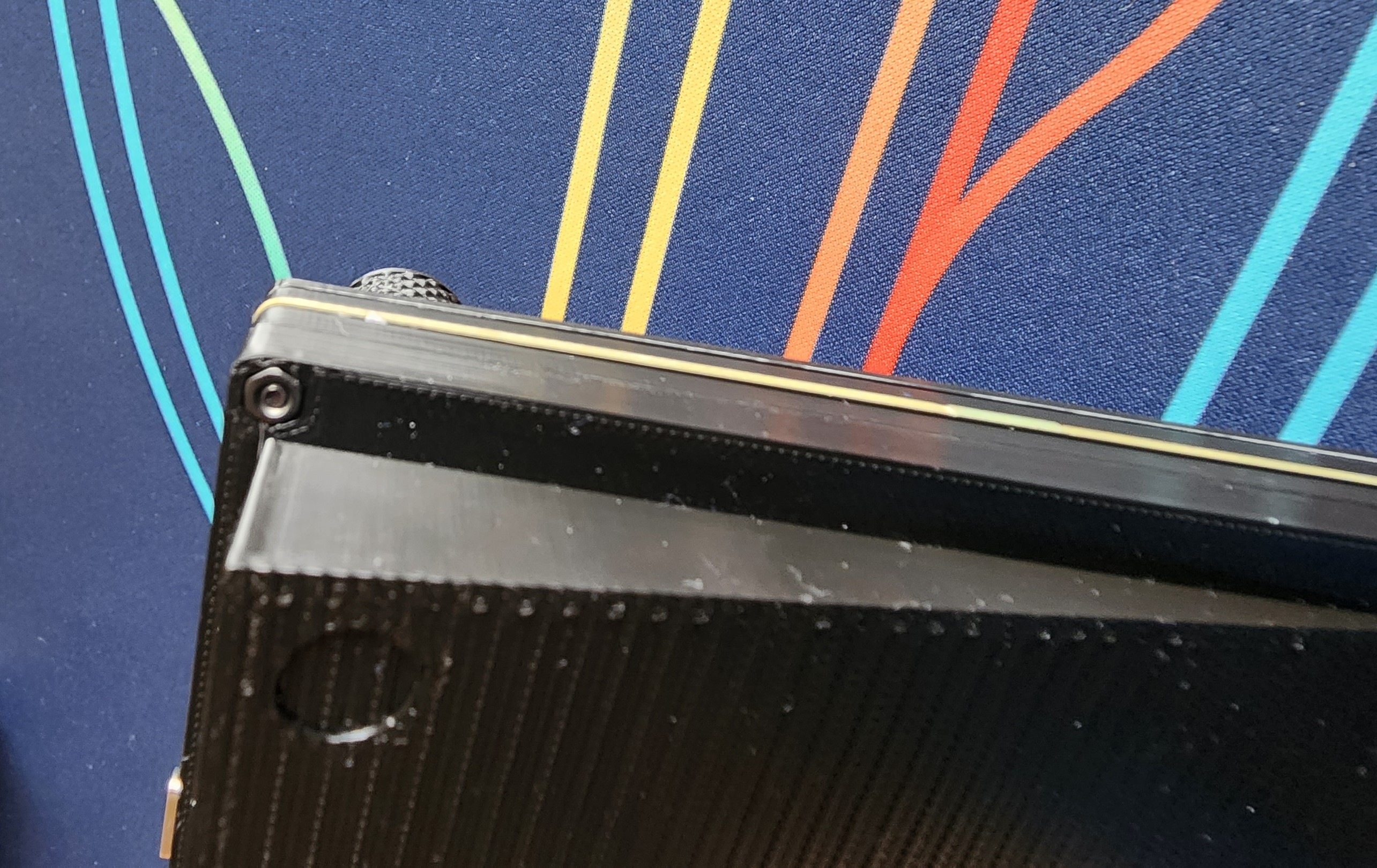
You will notice that there is a small notch on this part, Be sure to line that notch up with R6 on the PCB as shown below:
The mid piece should look like the following once installed:
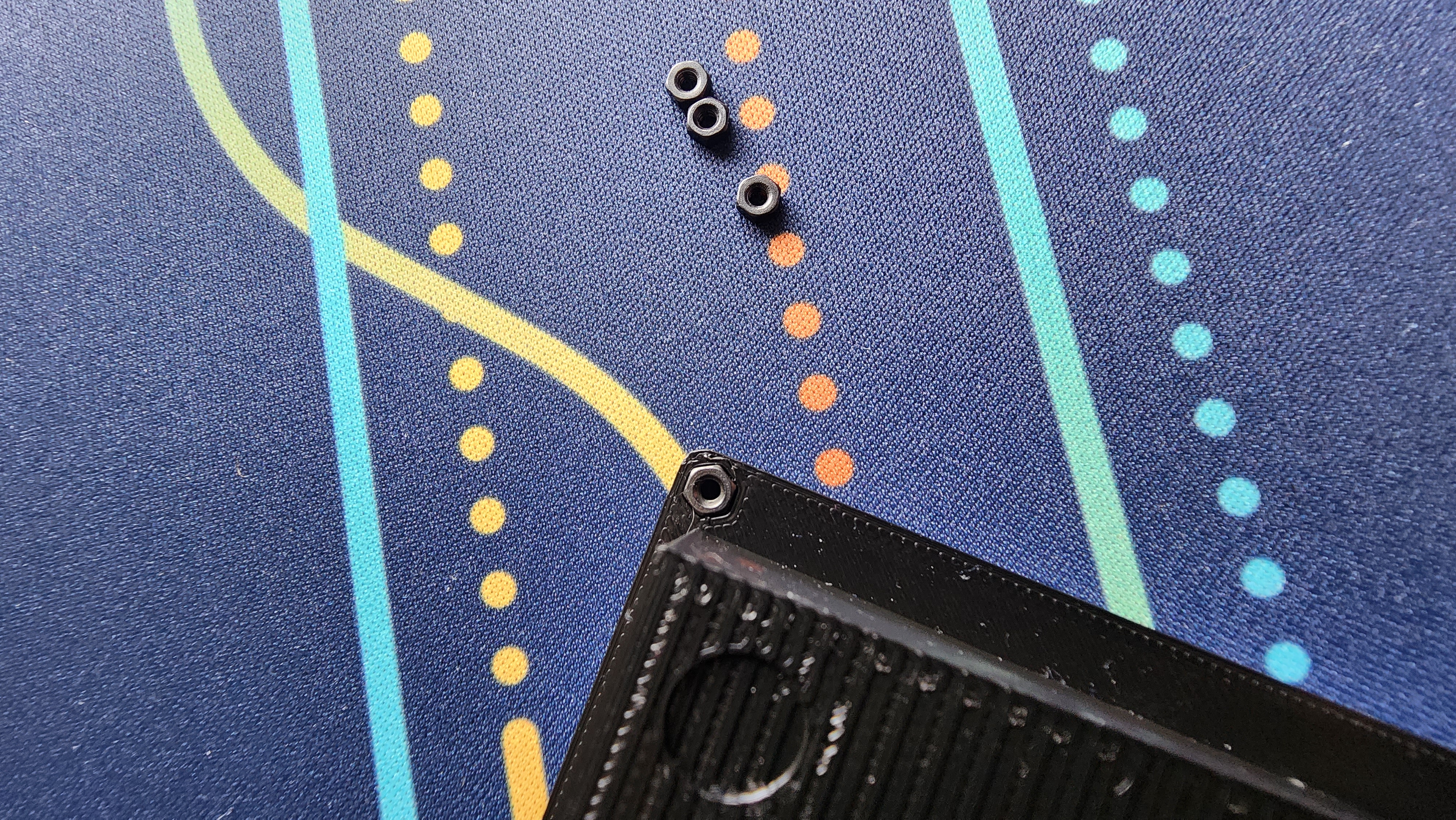
First, insert the 4 M2 nuts into each nut hole on the bottom piece as shown below:
Next grab the bottom piece and screw it on to the USB mid piece as shown below. The thicker part of the bottom piece should be facing the USB cutout.
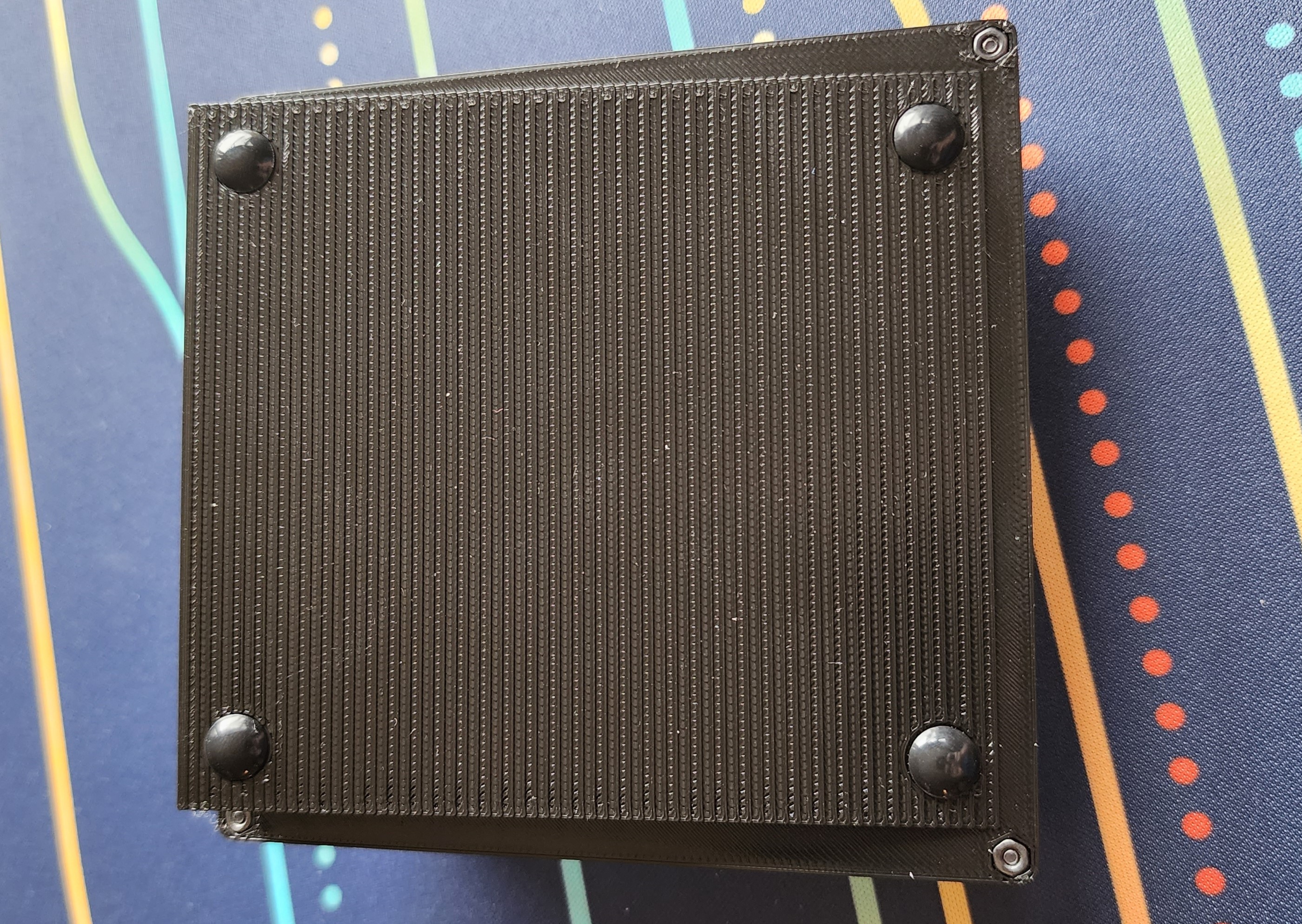
Then, install the 4 rubber bumpons in the 4 holes on the bottom piece as shown below:
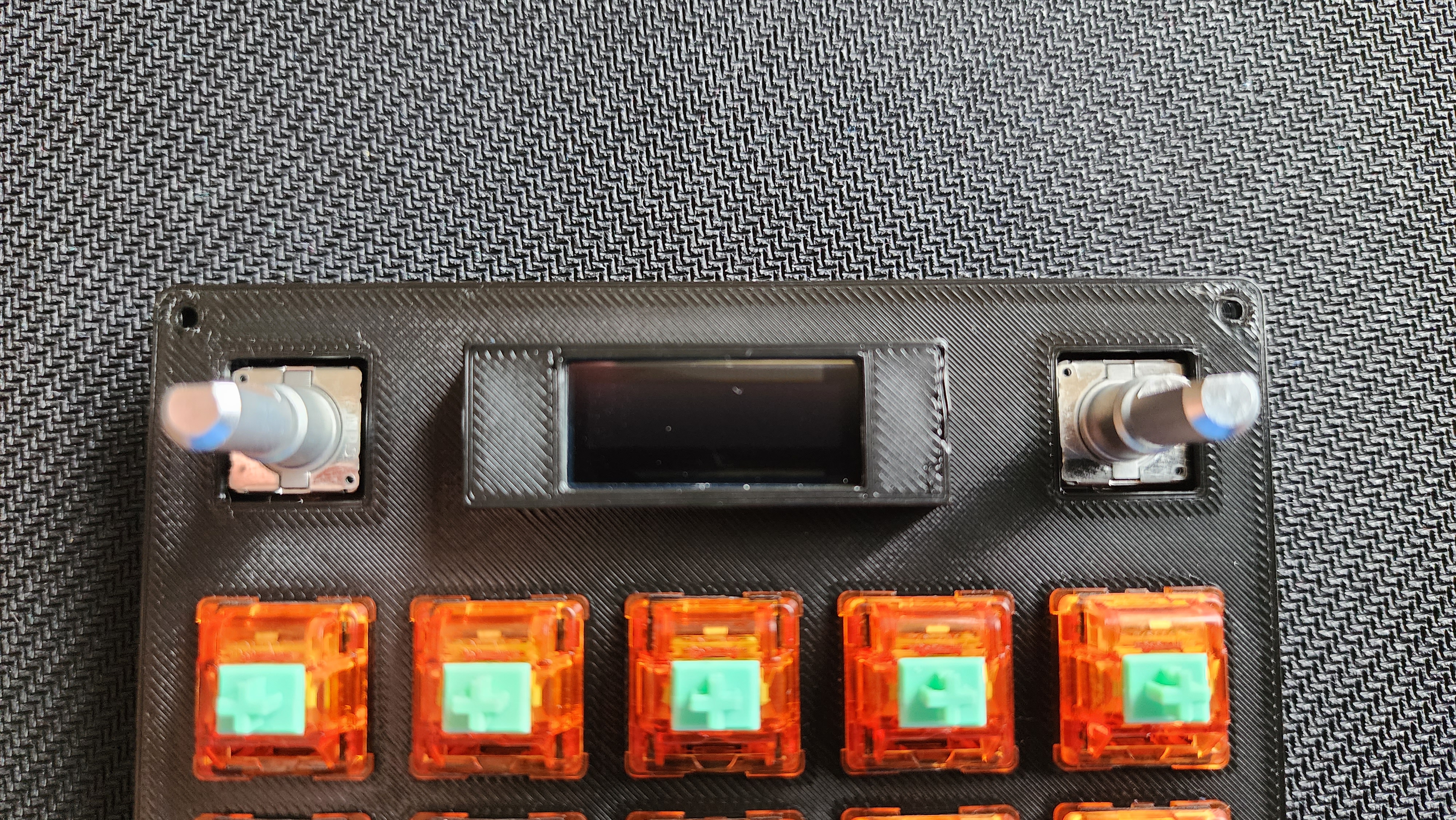
Next, grab the 2 knobs and press-fit them onto the encoders. These are a tight fit, so you may need to use a bit of force.
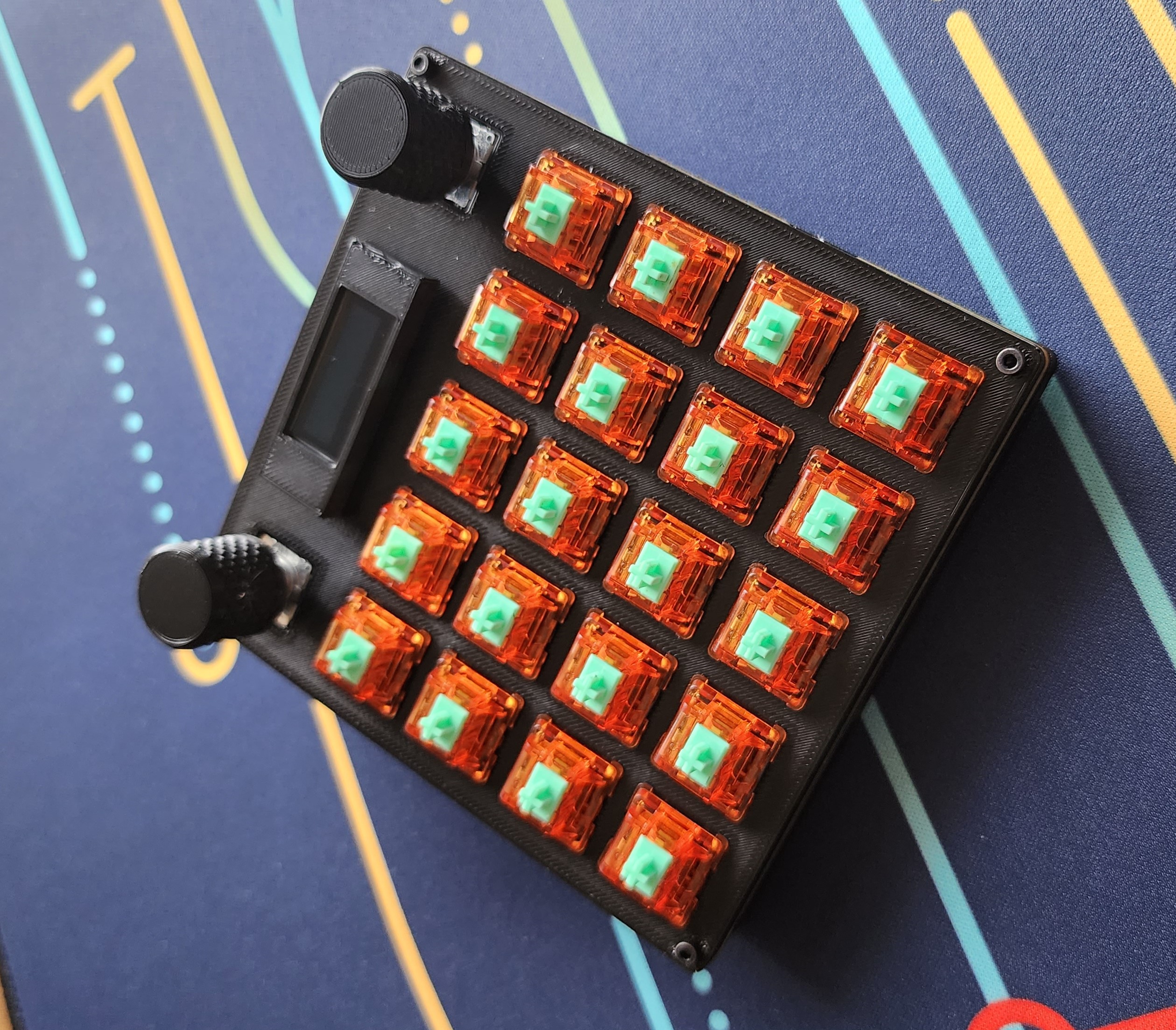
Finally, install your key caps of choice by press-fitting them onto the top of the switches!
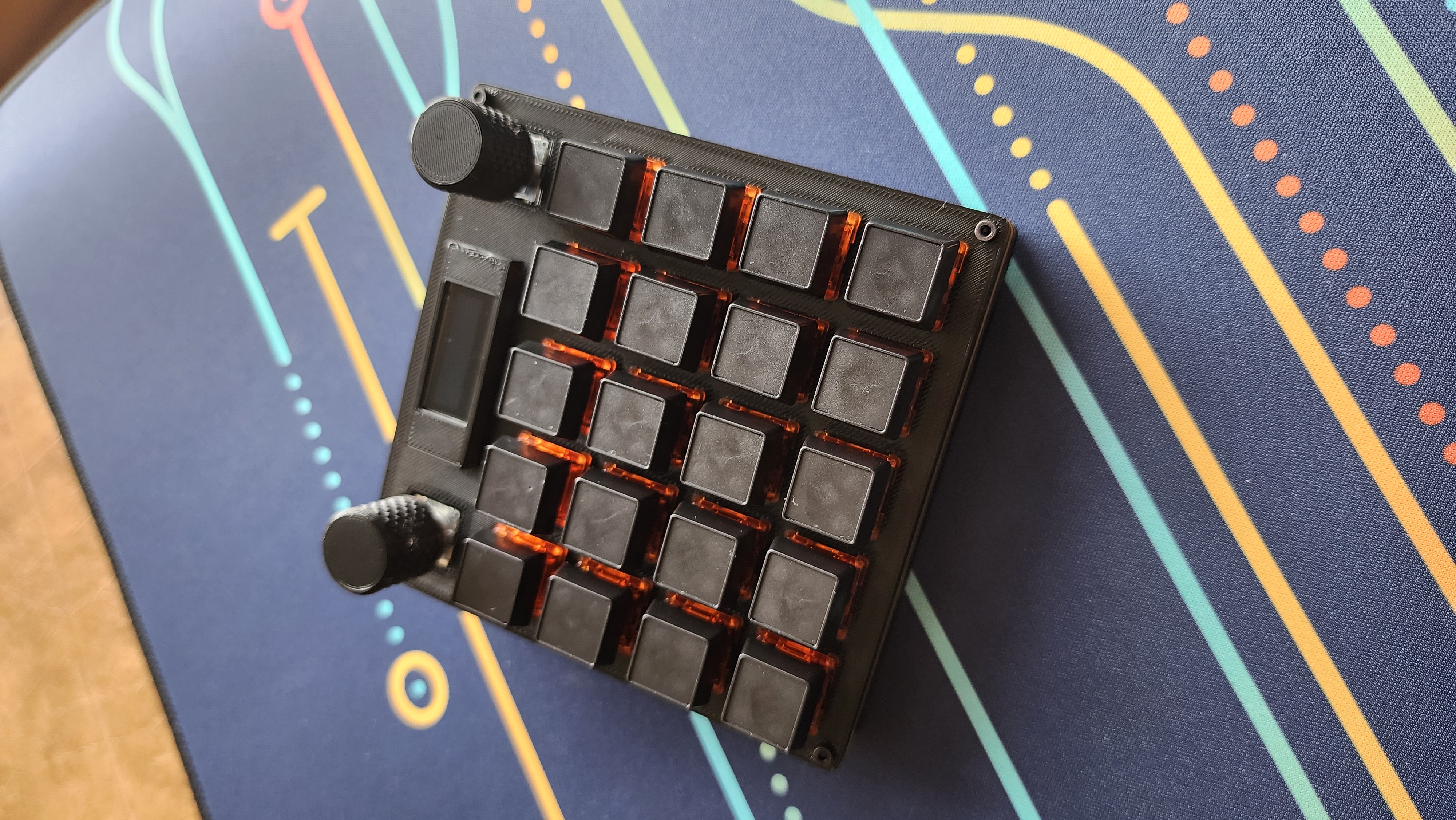
That’s it! You have now successfully assembled your Blue Team Pad!